4 20ma Transducer Wiring 4 20ma Signal Generator Circuit Dia
4 20ma pressure transducer wiring diagram database 4-20 wiring Fundamentals, system design, and setup for the 4 to 20 ma current loop
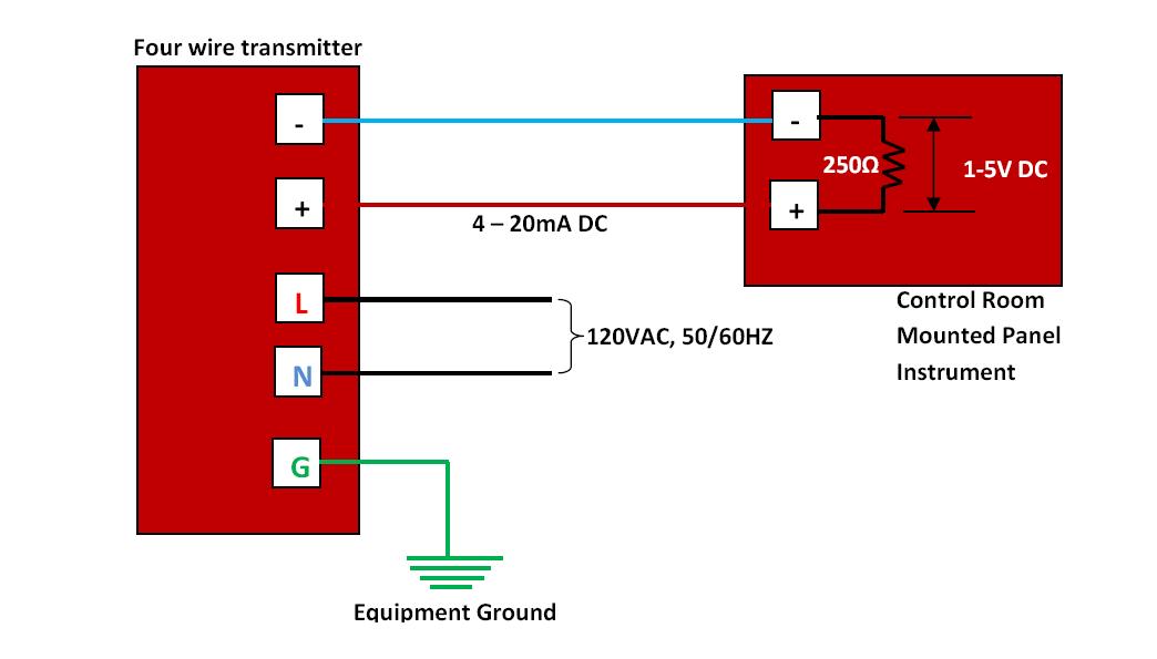
How to do the 4-20mA Wiring? | Instrumentation and Control Engineering
How to wire a 4-20ma transmitter?|4wire & 2wire (loop powered How to do the 4-20ma wiring? 4 to 20 ma current loop output signal
4 to 20 ma current loop output signal
4 wire pressure transducer wiring diagramWiring 20ma output schematic sensors Pressure transducer wiring diagram20ma wiring transmitter signal output wire sensor transducer resistor parallel loops 5vdc wires arduino.
Loop powered 4-20ma wiringPressure transducer 4 20ma test and troubleshooting guide 4 20ma pressure transducer wiring diagram databaseCurrenttrans 0-50a/4-20ma.

4-20 wiring
20ma transmitter works ma loop current process animation principle 20 circuit schematic gif instrumentation working converter tools signals point dcTest equipment parts & accessories business & industrial 0-1000 ohm to Currenttrans 0-5a/4-20ma4 20ma wiring diagram.
Quick guide! pressure transducer wiring: 2 wire,3 wire,4 wireD105: connecting the sensor with a 4-20ma current loop / main / smart Wiring diagram for 4-20ma pressure transducer explained20ma signal converter rs232 voltage 5vdc resistance vdc volt supply resistor ohm volts sensorsone required allow.

Wit wire transducer wiring diagram ma transmitter wiring types
4-20ma pressure transducer wiring diagram for your needsPressure transducer 4 20ma test and troubleshooting guide 20ma sensor d105 connecting maic4-20 ma transmitter wiring: 4wire transmitter connection & 2wire loop.
4-20 ma process control loopsBasics of the 4 How a 4-20 ma transmitter works?Loop control ma 20 current valve positioner loops process 20ma transmitter flow controller position feedback dcs smart connected using example.

Current transducer circuit diagram
2-wire 4-20 ma sensor transmitters: background and compliance voltageCurrent 20ma ac 5a 50a transducers input devices sensors sensor transducer 42l control automation direct 4 20ma signal generator circuit diagramPressure transducer wiring diagram differential 20ma.
Current 20ma ac 5a transducers input 50a devices sensors sensor transducer 42l control automation direct4-20ma output signal .


4 20ma Wiring Diagram

Loop Powered 4-20ma Wiring

Wit Wire Transducer Wiring Diagram Ma Transmitter Wiring Types | My XXX

How to do the 4-20mA Wiring? | Instrumentation and Control Engineering

Wiring Diagram for 4-20mA Pressure Transducer explained
4 Wire Pressure Transducer Wiring Diagram

D105: Connecting the sensor with a 4-20mA current loop / Main / smart

CurrentTrans 0-50A/4-20ma - AcuAmp AC Current Transducers - Current